In this tutorial, we will use the Geometer’s Sketchpad version to mimic the compass and straightedge construction tool we use in elementary geometry.
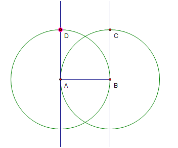
The idea in constructing a square is to use the radii of congruent circles. Before beginning the construction, see Figure 3 so that you will have an idea of what we are going to do. In Figure 4, segment AB is created, then two congruent circles, one with center A and passing through B, the other with center B passing through point A. The intersections of the circle and the line (points C and D) are the third and the fourth vertex of the square.
Step-by-Step Constructions
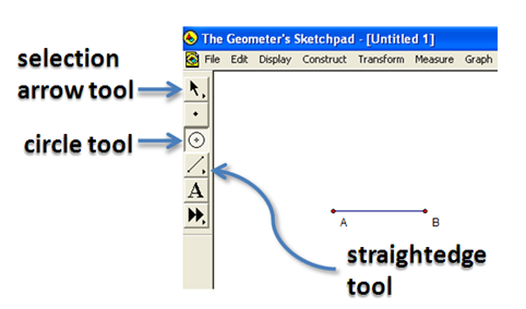
1.) Click the straightedge tool and select Segment Tool, then click two different locations on the drawing area.
2.) Click the Selection Arrow Tool, click on a blank space in the drawing pad to deselect the segment. To show the label of the two points, select the two points, click the Display menu, then click Show labels. Notice that GSP names the points alphabetically – the first A and the other B.

Figure 1 – Segment AB and the GSP toolbar.
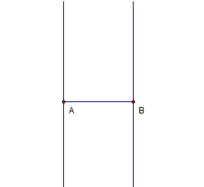
3.) To construct two lines perpendicular to segment AB, one passing through A and the other through B, click the segment (be sure that the two points are also selected), click the Construct menu, then click Perpendicular lines. Your construction should look like the one shown in Figure 1.

Figure 2 – Segment AB with lines perpendicular to it passing through its endpoints.
4.) Next, we will construct a circle with center B passing through A. To do this, click the circle tool, click point B and then click point A.
5.) We will now intersect the circle and the line passing through point B. To do this, click the Point tool, hover over the intersection of the circle and the line through B, wait for the two objects to change their color to cyan, then click their intersection.
6.) To display the label of the third point, with the third point selected, click the Display menu, then click Show label.

Figure 3 – Point C is the intersection of the circle and the line passing through B.
7.) Next, create a circle with center A and passing through B. Refer to step 4.
8.) Intersect the line passing through A and the circle with center A to construct point D.
9.) Show the label of the fourth point.

Figure 4 – ABCD is going to be the vertices of the squares.
10.) Next, we will hide the circles and the lines. Click the Selection Arrow tool, click the two circles and the two lines, then click Hide Path Objects.
11.) To form the square, use the Segment tool to connect the vertices of the square.
12.) Move the vertices of the square and observe what happens. Explain why your observation is such.


