GeoGebra Tutorial 3 – Constructing a Square
This is the third tutorial of the GeoGebra Intermediate Tutorial Series and the fourth part of the GeoGebra Basic Construction Series. If this is your first time to use GeoGebra, I strongly suggest that you read the GeoGebra Essentials Series. This tutorial, answers the following problem using GeoGebra.
Problem: How will you draw an equilateral triangle without using the Regular polygon tool?
In this tutorial, we mimic compass and straightedge construction using the Circle tool, the Parallel Line tool, the Perpendicular Line tool of GeoGebra to construct a square instead of using the Regular Polygon tool. We will also reinforce the use of the Angle tool, this time, learn how to use it to measure angle using three points.

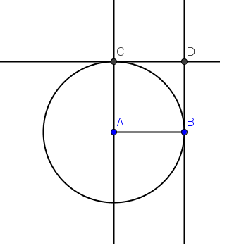
Figure 1 – Square formed from radii of a circle
The idea of our construction is to construct a circle with radius AB and construct lines parallel and perpendicular to it to form our square.
In the tutorial below, menu commands, located in the menu bar, are in brown bold text, and submenus are denoted by the > symbol. For example, Options>Labeling> New Points Only means, click the Options menu, choose Labeling from the list, then select New Points Only. The GeoGebra tools are denoted by orange texts. For example, New Point means the new point tool.
| 1.) Open GeoGebra and select Geometry from the Perspective menu on the Sidebar. | |
| 2.) To construct radius AB, select the Segment between Two Points tool and click two distinct places on the Graphics view. | |
| 3.) If the labels of the points are not displayed, click the Move tool right click each point and click Show label from the context menu. | |
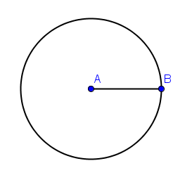
4.) To construct a circle with center A passing through B, select the Circle with Center through Point tool, click point A, then click point B. After step 4, your drawing should look like the one shown in Figure 2.
 Figure 2 – Circle with center A and passing through B |
|
| 5.) To construct a line perpendicular to AB and passing through A, click the Perpendicular Line tool, click segment AB then click point A. | |
|
|
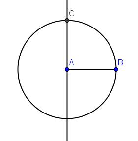
6.) To intersect the circle and the line, use the New Point tool and click one of the intersections. If the label of the third point is not shown, right click the point, then click Show label. After step 6, your drawing should look like the one shown in Figure 3.
 Figure 3 – Circle with radius AB and a line perpendicular to AB passing through A
|
| 7.) Next, we construct a line parallel to AB then passing through C. To do this, select the Parallel Line tool, click segment AB (not the points), then click point C. | |
|
|
8.) Now, we construct a line parallel to AC and passing through point B. To do this, with the Parallel Line tool till active, click line AC then click point B. |
|
|
9.) To construct the fourth vertex, select the Intersect Two Objects tool, click the line passing through B and the line perpendicular to it. After step 9, your drawing should look like the one shown in Figure 3.
 Figure 3 – Square formed from radii a circle |
| 10.) Using the Move tool, move point A or point B. What do you observe? | |
| 11.) Next we hide all the objects except the four points and segment AB. To do this, right click the objects that we are going to hide, and then uncheck Show Object from the context menu. | |
|
|
12.) To complete the square, connect points A and C, points C and D, and points D and B with the Segment between Two Points tool. |
| 13. To verify that the quadrilateral that we created is indeed a square, right click each side and click Object Properties. This will display the Preferences window. | |
| 14. In the Preferences window, select the Basic tab. Be sure that the Show label check box is checked and choose Value from the Show label drop down list box. (see the last figure in Tutorial 2) | |
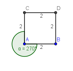
15. To measure angle A, click the Angle tool, and click the vertices in the following order: point C, point A and then point B (or B, then A, then C).
 Figure 4 – Square ABCD with a reflex angle on vertex A
|
|
| 16. In case the angle formed is a reflex angle, right click the symbol (the green sector), click on Object Properties on the context menu. This will display the Preferences window. | |
| 17. In the Basic tab of the Preferences window, choose 0˚ and 180˚ and the click the Close button. | |
| 18. Measure the other the angles using the Angle tool. Move point A or point B. What do you observe? | |
| 19. Explain why the construction above always results to a square. |