Introducing Math Lite

I would like to introduce a new category of articles called Math Lite. Math Lite will include the lighter part of mathematics, such as its connection to different fields especially in the arts and nature.  The objective of Math Lite is to show the readers the beauty of mathematics, to make them love it, or at least appreciate it  (good luck to me), and to show them the vastness of its application.

Contrary to my other posts, Math Lite will not discuss mathematics content. Math Lite will include math-related photos, videos, poems, jokes, quotations, or anything under the sun.

Math Lite articles will be posted every Saturday.

GeoGebra Tutorial 15 – Circle Area Approximation and Circumscribed Polygons

This is the continuation of GeoGebra Tutorial 14 – Circle Area Approximation and Inscribed Polygons.  You must finish the said tutorial before doing this because you will use the output file. If you want to follow this tutorial step-by-step, you have to download first the output file of the previous tutorial (go to the output file, click File>Save).

If you want to see the final output of this tutorial, click here.

Step-by-Step Instructions

1. Set the sliders to n = 3 and r = 3 to construct a circle with radius 3 and an inscribed triangle.
2. To construct a line tangent to the point B at (3,0), select the Tangents tool, click point B and click the circumference of the circle.

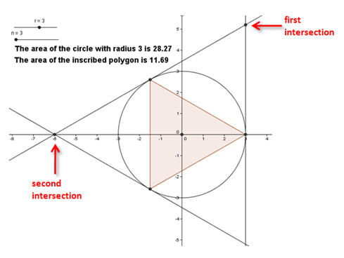
3. Using the steps in 2, create two more tangents, passing through the two vertices of the triangle; that is, with the Tangent tool selected, click the circle and the point on the circle. After step 3, your drawing should look like the Figure 1.
4. Select the Intersect two objects tool, and click the two lines intersecting at the first quadrant, then click the two lines intersecting at (-6,0) to intersect them.

Figure 1

5. Now, right click  one of the tangent lines and click Show Object from the context menu to hide it.  Hide the other two tangent lines.
6. We now create a circumscribed polygon using the Regular Polygon tool. To do this, click the Regular Polygon tool, and click the first intersection and click the second intersections of tangents to reveal the Regular Polygon dialog box.
7. In the Points text box, type n.This means, that whatever the polygon that is inscribed in the circle, that also will be the polygon that will circumscribe it.
8. Use the text tool to display the area of the circumscribed polygon as shown in Figure 2.

Figure 2

9. Adjust the sliders n = 3 and r = 1. What is the area of the circle?
10.  If you want to change the maximum number of sides, right click Slider n and click Properties. This will display the Slider dialog box.
11.  In the Properties window, click  the Slider tab, change the maximum value to 100, then click the Close button.

12.  Move the sliders and observe the relationship of the areas of the three objects. What conjectures can you make from your observations?

Geometer’s Sketchpad Tutorial 4 – Constructing a Square

In this tutorial, we will use the Geometer’s Sketchpad version to mimic the compass and straightedge construction tool we use in elementary geometry.

The idea in constructing a square is to use the radii of congruent circles. Before beginning the construction, see Figure 3 so that you will have an idea of what we are going to do. In Figure 4, segment AB is created, then two congruent circles, one with center A and passing through B, the other with center B passing through point A.  The intersections of the circle and the line (points C and D) are the third and the fourth vertex of the square.

Step-by-Step Constructions

1.) Click the straightedge tool and select Segment Tool, then click two different locations on the drawing area.
2.) Click the Selection Arrow Tool, click on a blank space in the drawing pad to deselect the segment. To show the label of the two points, select the two points, click the Display menu, then click Show labels. Notice that GSP names the points alphabetically – the first A and the other B.
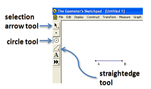
Figure 1 – Segment AB and the GSP toolbar.

3.) To construct two lines perpendicular to segment AB, one passing through A and the other through B, click the segment (be sure that the two points are also selected), click the Construct menu, then click Perpendicular lines. Your construction should look like the one shown in Figure 1.
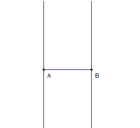
Figure 2 – Segment AB with lines perpendicular to it passing through its endpoints.

4.) Next, we will construct a circle with center B passing through A. To do this, click the circle tool, click point B and then click point A.
5.) We will now intersect the circle and the line passing through point B. To do this, click the Point tool, hover over the intersection of the circle and the line through B, wait for the two objects to change their color to cyan, then click their intersection.
6.) To display the label of the third point, with the third point selected, click the Display menu, then click Show label.

Figure 3 – Point C is the intersection of the circle and the line passing through B.

7.) Next, create a circle with center A and passing through B. Refer to step 4.
8.) Intersect the line passing through A and the circle with center A to construct point D.
9.) Show the label of the fourth point.
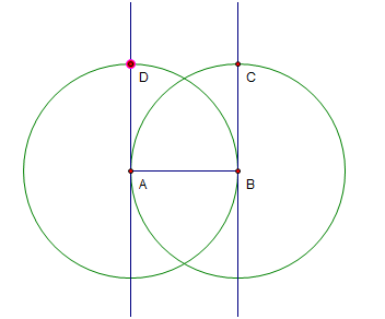
Figure 4 – ABCD is going to be the vertices of the squares.

10.) Next, we will hide the circles and the lines. Click the Selection Arrow tool, click the two circles and the two lines, then click Hide Path Objects.
11.) To form the square, use the Segment tool to connect the vertices of the square.
12.) Move the vertices of the square and observe what happens.  Explain why your observation is such.

1 2 3 4 5 6