Geometer’s Sketchpad Sketches at Sketch Exchange

Before I became a GeoGebra user, I used The Geometer’s Sketchpad. I migrated to GeoGebra because aside from it is free, it is more friendly to students. Geometer’s Sketchpad requires a little mathematical maturity and knowledge of geometric constructions. I still like Geometer’s Sketchpad,  GeoGebra is getting and better.

geometer's sketchpad

Last month, I have shared to you more than 12000 free dynamic applets from GeoGebraTube and more than a year ago, I have also mentioned more than 7000 demonstrations from Wolfram. To add to the list of dynamic geometry resources, The Geometer’s Sketchpad has also created its library of “sketches” in Sketch Exchange.  Sketch Exchange as of this writing has more than 500 sketches available.  Just like GeoGebraTube and Wolfram Demonstrations, it is a place where GSP users can share sketches, tips, and tutorials.

Most of the sketches in Sketch Exchange requires Geometer’s Sketchpad 5.05, a free upgrade if you have Sketchpad 5.

WinGeom Tutorial 2 – Constructing an Equilateral Triangle

In the last Wingeom tutorial, we have learned about the Midline theorem and how to use the basic tools of Wingeom such as the point and segment.  In this tutorial, we are going to construct an equilateral triangle by mimicking compass and straightedge construction.  In doing the construction, we will learn how to use the circle tool, and how to delete (or strictly speaking, hide) objects.
  1. Double click the Wingeom icon to open the Wingeom window. If the tip window appears, click the Close button.
  2. Top open the drawing window, click the Window menu and then click 2-dim or press the F2 key on your keyboard. When the drawing window appears, click the Maximize button.
  3. To display the Wingeom drawing tools, click the Btns menu, then click Toolbar.
  4. First, we will construct two points which will be the centers of our circle.  To construct the two points, select the segments option button on the toolbar, then right click two distinct places in the drawing window. Notice that letters  A and B appear in your drawing window.
  5. Figure 1 – The Drawing Window and the Wingeom Toolbar.

  6. To construct a circle with center A and passing through point B, select the circles option button in the tool bar, point at A, hold the left mouse button, slide the mouse pointer to B and then release the mouse button. » Read more

CaR Tutorial 2 – The MidSegment Theorem

In the previous CaR tutorial, we constructed and isosceles triangle. In this tutorial we are going to explore the properties of the segment connecting the midpoints of its two sides. In this tutorial we are going to learn the following:

  • use the move tool, triangle tool and segment tool
  • find the midpoint of two a segment
  • measure angles using the angle tool
  • edit properties and reveal measures of angles and segments

Construction Steps

1.) Open CaR. We will not need the Coordinate axes so click the Show grid icon until the Show the Grid icon until the grid or axes is not shown.
2.) Click the Triangle tool and click three different points on the drawing pad.
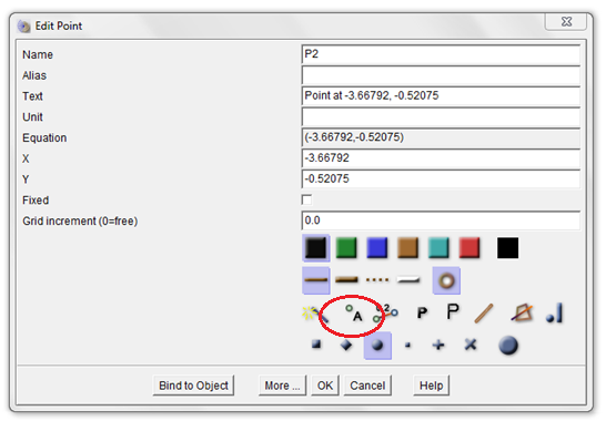
3.) Click the Move tool and right click one of the points to display the Edit Point dialog box. In the Name text box, change the name to A, then click the Show object names button (enclosed with red ellipse in Figure 1).

Figure 1 – The Edit Point dialog box.

4.) Change the name of the other two points to B and C.
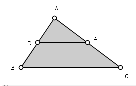
5.) Click the midpoint tool, click point A and click point B to get the midpoint of AB. Now, get the midpoint of BC. Rename the midpoint of AB to E and the midpoint of AC to F (Refer to step 3). Your drawing should look like Figure 2.

Figure 2 – Triangle ABC with midpoints D and E.

6.) Right click and drag the labels to adjust their positions. Using the Move tool, move the vertices of the triangle. What do you observe?
7.) We will see the relationship of the angles and the segments in triangle ABC. We will measure the angle first. To measure angle ADE, click the points in the following order: point A, point B and point C. After this step, you will see the angle symbol at angle ADE.
8.) To display the measure of the angle, click the Move tool and right click the angle symbol. This will display the Edit Angle dialog box shown in Figure 2.
9.) To display the measure of the angle, click the Show object values icon. Then click the smallest angle symbol size to reduce the angle size. Now, click the OK button to apply changes.

Figure 3 – The Edit Angle dialog box.

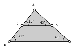
10.)  Using step 8-9, measure angles ABC, ACB and AED. After measuring, your drawing should look like the figure below.

11.)  Using the Move tool, drag the vertices of the triangle. What do you observe?
12.)  Based on the measures of the angles shown in your drawing, what can you say about segment DE and segment BC?
13. ) Now, we will see if there is a relationship between the length of the segments in triangle ABC. To reveal the measure of DE, use the Move tool and right click the segment. This will reveal the Edit Line, Ray, Segment dialog box as shown in Figure 3.

Figure 5 - The Edit Line, Ray, Segment dialog box.

14.)  In the Edit Line, Ray, Segment dialog box, click the Show object values button.
15.)  Using steps 13-14, display the length of segment BC.
16.)  What can you observe about the relationship of segments DE and BC?
17.)  Move the vertices of the triangle. Are your observations still the same?
18.)  Make a conjecture about your observations above.
1 2