 |
1.) Open CaR. We will not need the Coordinate axes so click the Show grid icon until the Show the Grid icon until the grid or axes is not shown. |
 |
2.) Click the Triangle tool and click three different points on the drawing pad. |
 |
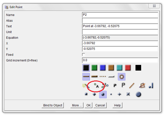
3.) Click the Move tool and right click one of the points to display the Edit Point dialog box. In the Name text box, change the name to A, then click the Show object names button (enclosed with red ellipse in Figure 1).
 Figure 1 – The Edit Point dialog box. |
|
4.) Change the name of the other two points to B and C. |
 |
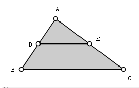
5.) Click the midpoint tool, click point A and click point B to get the midpoint of AB. Now, get the midpoint of BC. Rename the midpoint of AB to E and the midpoint of AC to F (Refer to step 3). Your drawing should look like Figure 2.
 Figure 2 – Triangle ABC with midpoints D and E. |
 |
6.) Right click and drag the labels to adjust their positions. Using the Move tool, move the vertices of the triangle. What do you observe? |
 |
7.) We will see the relationship of the angles and the segments in triangle ABC. We will measure the angle first. To measure angle ADE, click the points in the following order: point A, point B and point C. After this step, you will see the angle symbol at angle ADE. |
 |
8.) To display the measure of the angle, click the Move tool and right click the angle symbol. This will display the Edit Angle dialog box shown in Figure 2. |
|
9.) To display the measure of the angle, click the Show object values icon. Then click the smallest angle symbol size to reduce the angle size. Now, click the OK button to apply changes.
 Figure 3 – The Edit Angle dialog box. |
|
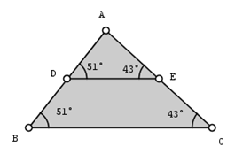
10.) Using step 8-9, measure angles ABC, ACB and AED. After measuring, your drawing should look like the figure below.

|
 |
11.) Using the Move tool, drag the vertices of the triangle. What do you observe? |
|
12.) Based on the measures of the angles shown in your drawing, what can you say about segment DE and segment BC? |
|
13. ) Now, we will see if there is a relationship between the length of the segments in triangle ABC. To reveal the measure of DE, use the Move tool and right click the segment. This will reveal the Edit Line, Ray, Segment dialog box as shown in Figure 3.
 Figure 5 - The Edit Line, Ray, Segment dialog box. |
 |
14.) In the Edit Line, Ray, Segment dialog box, click the Show object values button. |
|
15.) Using steps 13-14, display the length of segment BC. |
|
16.) What can you observe about the relationship of segments DE and BC? |
 |
17.) Move the vertices of the triangle. Are your observations still the same? |
|
18.) Make a conjecture about your observations above. |


