GeoGebra Tutorial 10 – Vectors and Tessellation

This is the 10th tutorial in the GeoGebra Intermediate Tutorial Series. If this is your first time to use GeoGebra, you might want to read first the GeoGebra Essentials Series.

This tutorial is the sequel of GeoGebra Tutorial 9 – Vector and Translation.  In this tutorial, we  use the idea of translation to tessellate  the plane. Tessellation is a process of covering a plane with no gaps and no overlaps.

The final output of our tutorial is shown in Figure 1 and the GeoGebra applet can be viewed here.

geogebra vector translation1

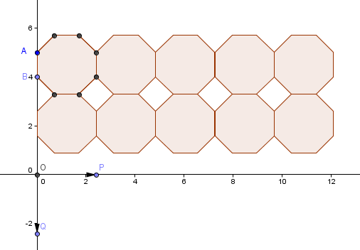
Figure 1 – Octagon and squares tessellating the plane.

To give you the whole picture, I have enumerated the summary of what we are going to do in this construction.

  1. Construct an octagon containing points A at (0,5) and B at (0,4).
  2. Draw point O at the origin which is the initial point of vector, P at the positive x-axis and vector Q at the negative y-axis. P and Q are the terminal points of the vectors.
  3. Draw vectors u (containing O and P) and v (containing O and Q).
  4. Translate the octagon to tessellate the plane using vector u.
  5. Translate all the created octagons down using vector v.
  6. Draw a square that will cover the space at the center of the 4 leftmost adjacent octagons.
  7. Translate the square to the right using vector u.

Construction Protocol

1.) Open GeoGebra and select Algebra & Graphics from the Perspectives menu
2.) Click the New Point tool and place two points in the coordinates given: A on (0,5) and B in (0,4).
3.) Select the Regular Polygon tool, click point A, then click point B to display the Regular Polygon dialog box. In the dialog box, type 8, then press the OK button. If the labels of the points and the segments are displayed, remove them by right clicking them and unchecking on Show label from the context menu.

Figure 2 – Octagon with containing segment AB.

4.) Next, we create three points which will be the initial and terminal points of the vector (see Figure 1). Click the New Point tool, click on the origin, click a point on the positive x-axis near the origin and the negative y-axis near the origin.
5.) We now rename the three points. To rename the point on the origin, right click it and click Rename from the context menu. In the Rename box, type O and press the OK button. Rename the point on the x-axis as P and the point on the y-axis Q.
6.) Now, to create vector u, select the Vector between Two Points tool, click on point O, then click on point P. To create vector v, with the Vector between Two Points tool still active, click point O and then click point Q to create vector v.
7.) To translate the octagon to the right, select the Translate Object by Vector tool, click the interior of the octagon, then click vector u.

8.) Adjust vector u such that the right vertical side of the first octagon coincides with the left vertical side of the translated octagon. Your drawing should look like Figure 3.

vector translation

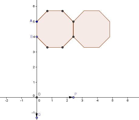
Figure 3 – An octagon and its translation using vector u.

9.) To translate another octagon, with the Translate Object by Vector tool still active, click the rightmost octagon, then click vector u. Repeat this step three times giving us 5 octagons with adjacent vertical sides.
10.)  Next, we translate the octagons down vertically. To do this, select the Translate Object by Vector tool, click the leftmost octagon and then click vector v. Adjust the translated octagon by moving point Q such that the lower horizontal side of the original octagon coincides with the upper horizontal side of the translated octagon.
11.)  Repeat step 10 until all the 5 octagons are translated down.  After step 11, your figure should look like Figure 1 with white squares.
12.)  The last part of the task is to cover the empty square spaces between octagons. To do this, click the Regular Polygon tool, click the two consecutive points of the leftmost square (on the side of the octagon) to display the Regular Polygon dialog box.
13.)  Type 4 as the number of Vertices and then click OK. If the square created is on the other side, undo the step, and reverse the order of the click.
14. ) To tessellate, click the square and then click vector u. Repeat the translation as you have done in step 9.


Tessellation: The Mathematics of Tiling

You have probably noticed that floors are usually tiled in squares or sometimes in rectangles.  What is so special about these shapes? What are the disadvantages of using other shapes?

The most important thing to consider in tiling is that the shape of the tiles should cover the floor without gaps and without overlaps. Probably, this condition will be satisfied easily if the tiles that are used have the same shape and the same size.

If we are going to use regular polygons in tiling, then we can use squares, equilateral triangles or regular hexagons as shown in Figure 2. These polygons will cover the floor without gaps and overlaps, and thus will minimize the need for cutting.

Figure 1 – A honeycomb is an example of hexagonal tiling.*

In mathematics, the term used for tiling a plane (floor in our context) with no gaps and no overlaps is tessellation. Of course, we are not the only one who realized the advantages of shapes that can tessellate. The bees create honeycombs in hexagonal tessellation as shown in Figure 1.

Figure 2 – Examples of regular polygons that can tile the floor without gaps and overlaps.

Note: If you are wondering how these beautiful diagrams were created, I have created a tutorial about it here.

Looking at Figure 3, we can see that not all regular polygons exhibit the property shown by polygons in Figure 2. It is clear that the regular polygons namely pentagons, heptagons and octagons do not tessellate the plane.

Figure 3 – Examples of polygons that cannot tessellate the plane.

From the discussion above, we want to ask the following questions:

  1. What are the properties of polygons that can tessellate the plane?
  2. Aside from equilateral triangles, squares and regular hexagons, what other polygons can tessellate the plane?


Delving Deeper

In Figure 4, notice that in order for a regular polygon to tessellate the plane, the sum of the interior angles that meet at a common point must equal 360 degrees.

Figure 4 – The Interior angles of polygons that can tessellate the plane add up to 360 degrees.

On the other hand, the three polygons in Figure 5 do not tessellate the plane. In the leftmost illustration, the measure of the interior angles of a regular pentagon is 108 degrees.  If we try to tile the plane, we can see that the measure of the three angles meeting at a common point add up to 324 degrees.  Now, this leaves an “exterior angle” of 36 degrees angle as shown. In the remaining part of this article, we will refer to this type of angle (denoted by red text measurements) as exterior angles.

As we increase the number of sides of a regular polygon, we also observe that we cannot make three interior angles meet at a common point without overlapping. This is shown in the center and rightmost illustration in Figure 5. Only two polygons can have their vertices attached at a common point without overlapping.

Figure 5 – Exterior angles produced by some polygons.

In the Angle sum of Polygon post, we have discussed that the sum of the interior angles of a polygon with n sides is described by the formula 180(n-2).  Since we have n congruent angles, it follows that each angle measures  \displaystyle\frac{180(n-2)}{n}. As a consequence, as the value of n increases, the measure of the interior angles increases. In effect, the measure of the exterior angle decreases as the value of n increases.

Figure 6 – Table showing properties of tessellating and non-tessellating polygons.

Looking at the table in Figure 6, we can see that polygons whose product of interior angles and the number of adjacent vertices is 360 tessellate. Consequently, the measure of their exterior angles is 0.

Furthermore, observe that as the number of sides of the polygons increases, the fewer the number of vertices that we can fix at a common point without the polygons overlapping.  Since all regular polygons with more than six sides have interior angles measuring greater than 120 degrees, placing their three interior angles at a common point will make two of them overlap.  This is because their angle sum would be greater than 360 degrees (we can verify this using the Tessellation GeoGebra applet).Thus, for polygons more than six sides, only two vertices can be placed adjacently without overlapping. Now, to tessellate, the two adjacent interior angles of these polygons must add up to 360 degrees, which means that each of them must equal 180 degrees. Of course, there is no such polygon. Hence, there is no way that we can tessellate the plane with regular polygons having number of sides greater than six. This proves that the only regular polygons that we can use to tessellate the plane are the three polygons shown in Figure 2.

Non-Regular Tessellations

We will not limit, of course, our creativity by using only regular polygons in tiling floors. The polygons shown in Figure 7 are some of the tiles which are not regular polygons. In the rightmost figure, we used octagons and squares in tiling, which is considered as a semi-regular tessellation.

Figure 7 – Example of non-regular polygon tessellation.

Going Beyond

Not all tessellations are created in the Euclidean plane.  In the leftmost illustration in Figure 8, the sphere is tessellated by a truncated icosidodecahedron.

Figure 8 – Tiling in the Spherical, Hyperbolic and Euclidean Plane**.

The center illustration is an example of tessellation of the hyperbolic plane, created by M.C. Escher and the rightmost illustration is another example of the tessellation of the Euclidean plane – a lso by M.C. Escher.

**********************************************************************

Photos used in this article:

*Buckfast Bee ”Source:”’ picture taken by Frank Mikley on 2006-07-23.  Adapted from the Wikimedia Commons file “Image:Buckfast_bee.jpg” http://upload.wikimedia.org/wikipedia/commons/1/1e/Buckfast_bee.jpg

**1. Spherical truncated Icosidodecahedron .Adapted from the Wikimedia Commons file “Image: Uniform_tiling_532-t012.png”

http://upload.wikimedia.org/wikipedia/en/5/55/Uniform_tiling_532-t012.png

**2. Circle Limit III by M. C. Escher (1959).

**3. Angles and Devils by M. C. Escher (1941).