Is there an SSA Congruence?

In the Triangle Congruence post, we discussed about ways to test if two triangles are congruent. The only theorems (or sometimes called postulates) that hold are the SSS, SAS and ASA congruence. We ended our discussion with the question about the AAS (or SAA), AAA and SSA (or ASS) congruence.

Let us try to explore the AAS case.  If we have two triangles (see first pair of in Figure 1), and two pairs of their angles (denoted by the blue and red circles) are congruent the third pair of angles (denoted by the yellow circles in the second pair) are also congruent. Hence, a pair of sides (both included in two pairs of congruent angles) are congruent, which is similar to the ASA congruence. Therefore AAS congruence holds and is equivalent to ASA congruence.

Figure 1 – AAS and ASA congruence postulates are equivalent.

In Figure 2, shown are triangles with three pairs of angles that are congruent. It is clear that the two triangles are not congruent. Therefore, AAA congruence does not hold.

Figure 2 – Triangles having three pairs of congruent angles.

Now, let us try the SSA congruence. Figure 3-A shows triangle ABC with sides and angle marked. We extend AC to the right hand side (see Figure 3-B), then rotate BC about point B (see Figure 3-C). We let C’ be the intersection of BC and the extended segment such that BC is congruent to BC’ (see Figure 3-D).

Figure 3 – Triangels having two pairs of sides and a pair of angles which are congruent.

Looking at Figure 3-A and Figure 3-D, two pairs of their sides and a pair of non-included angles are congruent, but the triangles are not congruent. Therefore, SSA (or ASS) congruence does not hold.

A Closer Look at the Midpoint Formula

Introduction

If we want to find the midpoint of segment CD in Figure 1, where the coordinates of points C and D are (-2,5) and (-2,1), it is clear that the length of CD is 5 - 1 = 4 units.  To determine the midpoint of CD, we want to get the coordinates of the point which is 2 units away from both points C and D.  Hence, we have to divide 5 - 1 = 4 by 2, and add the result to 1 or subtract the result from 5.  Summarizing, the expression that would describe the value of the y-coordinate of the midpoint would be \displaystyle\frac{(5 - 1)}{2} + 1 or  5 - \displaystyle\frac{(5 - 1)}{2}. This means that the midpoint of CD is (0,2).

If we want to get the midpoint of AB, using the same reasoning above, the expression that would describe the x-coordinate of the midpoint would be \displaystyle\frac{(6 - 3)}{2} + 3 or 6 - \displaystyle\frac{(6 - 3)}{2}. This means that the midpoint of AB is (1.5,0).

Figure 1 – Horizontal line AB and vertical line CD in the coordinate plane.

Generalizing our observation above, if we have a vertical segment with their endpoints having coordinates (a, y_1) and (a,y_2) (see Figure 2), we can get its midpoint  using the following formula \displaystyle\frac{y_2 - y_1}{2} + y_1  or y_2 - \displaystyle\frac{y_2 - y_1}{2} + y_1

Figure 2 – Generalized coordinates of a vertical and a horizontal line.

Simplifying, both the expressions above result to \displaystyle\frac{y_2 + y_1}{2}. Similarly, for a horizontal segment with endpoints having coordinates (x_1, b) and (x_2, b) can be computed by the expression \displaystyle\frac{x_1 + x_2}{2}.

Midpoint of a Slanting Segment

The preceding derivations are only valid for vertical and horizontal segments. In Figure 3, segment AB is neither horizontal nor vertical. To investigate the midpoint of AB, we draw vertical segment PQ coinciding with the y-axis with endpoints having y-coordinates the same as those of the y-coordinates of segment AB (see Figure 3). We also draw a horizontal line RS coinciding the x-axis with endpoints having  x-coordinates the same as those of the x-coordinates of segment AB. Looking at Figure 3, it is clear that the coordinates of the midpoint of the PQ is (0,3).

If we draw a horizontal line from (0,3) towards segment AB (see yellow dashed segment), and draw a vertical line from the intersection M to segment RS, it seems that the intersection of the yellow dashed line and segment RS is (3.5,0) which is the midpoint of RS. From here, it is tempting to ask the following question:

“If the midpoint of PQ is (0,3) and the midpoint of RS is (3.5,0), is the midpoint of AB, (3.5,3)?

Figure 3 – A non-horizontal segment AB with midpoint M.

Generalizing the questions above, we might want to ask “If the midpoint the point with coordinates A (x_1,y_1) and B (x_2, y_2) equal to (\displaystyle\frac {x_1 + x_2}{2}, \displaystyle\frac{y_1 + y_2}{2})?”

If we extend the QA and the horizontal yellow dashed line to the right, we can from two right triangles as shown in Figure 4. From the statements above, we want to show that point M is the midpoint of AB.

To show that M is the midpoint of AB, it is sufficient to show that AM is congruent to MB.  This leads us to Figure 5, where we label the right angles of the two triangles T and U. We will now show that triangle AUM is congruent to triangle MTB. If so, then we can show that AM is congruent to MB since they are the corresponding sides of the given triangles.

Proof that AUM is congruent to MTB

Since PB and MT are horizontal segments, we can consider AB as a transversal of parallel segments PB and the segment containing MT.  It follows that angle TBM and angle UMA are congruent because they are corresponding angles. It is also clear that BT is congruent to MU, and angle T is congruent to angle U since they are both right angles. Therefore, by the ASA congruence theorem, AUM is congruent to MTB.  (For an explanation of parallel lines and transversals, click here).

Since corresponding parts of congruent triangles are congruent, AM is congruent to MB. Hence, M is the midpoint of AB.

Figure 5 – The triangle produced by extending the horizontal lines passing through the three points.

Note that our proof did not talk about coordinates, but the general case.  That is, if the coordinates of A are ( x_1, x_2) and the coordinates of B are (y_1, y_2), the coordinates of M is equal to
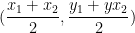
 (\displaystyle\frac{x_1 + x_2}{2},\displaystyle\frac{y_1 +yx_2}{2} ).

Delving Deeper

There are also other ways to show that the midpoint of AB is M.  ( x_1,y_1) and ( x_2,y_2) lies on  the midpoint formula. The details of the solutions are left to the reader as an exercise.

  • From Figure 3, draw two right triangles with hypotenuse AM and hypotenuse AB and show that AM is half of AB.
  • Using the distance formula, show that the distance between point A and point M is the same as the distance between point M and point B.
  • Show that AM and MB has the same slope.
  • Get the equation of the line containing AB, and substitute the coordinates of M to the equation of line AB.

GeoGebra Tutorial 7 – Sliders and Rotation

This is the seventh tutorial of the GeoGebra Intermediate Tutorial Series. If this is your first time to use GeoGebra, please read the GeoGebra Essentials Series.

In the Graphs and Sliders posts (click here and here ), we have discussed how to use number sliders.  In this tutorial, we use the Angle slider to rotate a triangle in order to show that its angle sum is 180 degrees. This is the same GeoGebra worksheet shown in my Parallel Lines and Transversals post, but we will change some of the labels. Although this tutorial is the seventh of the GeoGebra Tutorial Series.

Figure 1 – Rotated triangles using sliders.

Construction Overview

The construction will start by drawing line AB and constructing triangle ABC using the Polygon tool. Afterwards, we reveal the interior angle measures of the triangle and create two angle sliders namely \alpha  and \beta. Next, we rotate the triangle 180 clockwise about the midpoint of BC producing triangle A’B’C’ (see Figure 1-B). We then repeat the process, and rotate triangle A’B’C’ 180 degrees clockwise about the midpoint of A’C’ to produce A’’B’’C’’.

Part I – Constructing Triangle ABC

1.) Open GeoGebra and select Geometry from the Perspectives menu.
2.) Click the Line through Two Points tool, and click two distinct locations on the Graphics view to construct line AB.
3.) If the labels of the points are not displayed, click the Move tool, right click each point and click Show label from the context menu.
4.) Click the New Point tool and construct a point C not on line AB.
5.) Display the name of the third point. GeoGebra would automatically name it C, otherwise right click and rename it C.
6.) Click the Polygon tool and click the points in the following order: point A, point B, point C, and click again on point A to close the polygon. Your drawing should look like Figure 1.

Figure 2 – Triangle ABC on line AB.

7.) Move the vertices of the polygon. What do you observe?
8.) Now we construct two angle sliders \alpha and \beta. To do this, click the Slider tool, and click on the Graphics view.
9.) In the Slider dialog box (see Figure 3), choose the Angle radio button, and then leave the name angle as \alpha.  In the Interval tab, choose 0° as minimum, 180° as maximum and 1°, and then click the Apply button when finished.

Figure 3 – The Slider dialog box

10.) Using steps 8-9, create another slider with the same specifications shown in Figure 3 and name it \beta. You can find the Greek letters by pressing the \alpha button located at the right of the text box.
11. ) We reveal the angle measures of the interior angles of the triangle, the change the colors of the angle symbols (green sectors). To do this, click the Angle tool and then click the interior of triangle ABC.
12.)  We now hide the measures of the angles. To do this, right click each angle symbol and uncheck Show label from the context menu.
13.  We set angle colors: angle A red, angle B blue and angle C green. To change the color of the angle symbol of angle A, right click the angle symbol (not point A) and click Object Properties from the context menu to display the Preferences window.
14.  In the Preferences window, click the Color tab and choose the color you want from the color palette then click the Close button.
15.  Change the color of angle B to blue and leave angle C as is.  Your drawing should look line Figure 1-A after step 15.

Part II – Rotating the Triangle

We already have the sliders ready. The next thing that we will do is to rotate the triangle. The idea is to create a rotation point. Our choice would be the midpoint of BC. That is because if we rotate ABC by 180 degrees producing A’B’C’, angle A’C’B’ will be adjacent to angle ABC (see Figure 1-B). This is also the idea when we rotate A’B’C producing A’’B’’C’’.

.

1.) To construct D, the midpoint of BC, click the Midpoint or Center tool, and click side BC (the segment, not the points).
2.) Note that we want ABC to rotate around D \alpha degrees clockwise. To do this, choose Rotate around a Point by Angle tool, click the interior of the triangle and click point D to reveal the Rotate Object dialog box.
3.) In the Rotate Object around Point by Angle dialog box, change the measure of the angle to \alphachoose the clockwise radio button, and then click the OK button.

Figure 4 – The Rotate Dialog Box

4.) Now move slider \alpha. What do you observe?
5.) Adjust slider \alpha to 90 degrees, and show the labels of the vertices of the rotated triangle. (Refer to Part I – Step 3).
6.) While the triangle is still rotated 90 degrees, click the Angle tool and click the interior of triangle A’B’C. Hide the labels of the angles symbols.
7.) Change the colors of the angle measures. Refer to Part I – Steps 13 through 15. Be sure that angle A and A’ have the same color, B and B’ have the same color, and C and Chave the same color. Your drawing should look like the drawing in Figure 6.

Figure 5 – The Rotated Triangle

Part III – Creating the Third Triangle

The idea of creating the third triangle is basically the same as that of creating the second triangle, so I will just enumerate the steps and left the construction as an exercise.

  1. Get the midpoint of A’C’. (Refer to Part II Step 1)
  2. Rotate triangle A’B’C’ \beta degrees clockwise around the midpoint of A’C’.  (Refer to Part II – Steps 2 – 3).
  3. Reveal the labels of the vertices of the third triangle which is A’’B’’C’’.  (Refer to Part II – Step 5 and Part I – Step 3).
  4. Reveal the angle symbols of triangle A’’B’’C’’.  (Refer to Part I – Step 11)
  5. Hide the labels of the angle symbols, and change the colors of the angle symbols of triangle A’’B’’C’’. (Refer to Part I – Step 13-15)

The explanation of the theory behind this construction is in my Parallel Lines and Transversal post.

1 17 18 19 20 21 23